| Issue 6 |
Corrosion is the enemy of most civil engineering structures, particularly maritime structures. Combating corrosion is fundamental in providing durable structures which will not become a liability in the future. This may sound like a statement of the obvious but corrosion is pervasive and has some surprising forms. I have used the analogy of warfare to illustrate this article. I intend to show that corrosion can be a wily enemy.
Since I came down in 1959 and joined the civil engineering profession, there has been widespread recognition of the importance of durability and the concept of whole life cost has become established. I may say that during my two years reading Engineering Science I don't recollect the topic of corrosion being mentioned, let alone learning about the corrosion processes. Perhaps this is not so surprising in view of the small amount of academic content in the subject; nevertheless, it is now so central to the design process that an awareness of it is essential. Certainly, it came to be a vital factor in my professional career designing maritime structures. It also provided a few sleepless nights worrying about structures, the design of which I had been involved with about 30 years ago, which we might have done better if we had been more aware of what the effects of corrosion might throw at us. Some of the tricks the enemy had in store for us were astonishing, as I will explain.
I spent most of my career designing maritime works, in particular, dry docks, piers and quays as well as the on-shore facilities for shipyards. During the years I was in consulting engineering, the ships, particularly oil tankers, got bigger and bigger. In the 1950s a large tanker would be of the order of 30,000 deadweight tonnes (dwt) carrying capacity; whereas by the 1980s there was a large number of tankers in excess of 300,000 dwt. Bigger ships need bigger dry docks for their repair and maintenance and this, of course, was good for dry dock designers. Our firm, TF Burns and Partners, now part of Royal Haskoning, was lucky to have, and still has, a pre-eminent position in the design of dry docks and has been involved with fifty or so dry docks. I was lucky enough to lead on the design of four of the largest dry docks in the world.
Dry docks are not glamorous structures, but they do present considerable challenges. Due to their nature, they are large below ground structures built close to water, usually sea water. To build them a deep excavation is required and, assuming the dry dock is to be constructed in the dry, it has to be dewatered as the excavation progresses. Depending on the ground, this can be a real challenge in itself; knowledge of the soils and their permeability is essential. There is at least one dry dock where some of the most reputable geotechnical experts got it dramatically wrong and it proved impossible to dewater the excavation, resulting in a contractual impasse which was only resolved by a complete redesign and the construction of the dry dock underwater! However, that is another story.
Having set the scene with dry docks, I want to highlight the severe corrosion conditions, which are encountered in all maritime structures of which dry docks are a prime example. The inside of a shiprepair dry dock is particularly corrosive with a seawater wetting and drying cycle of four or five days. All ferrous fittings are highly vulnerable, particularly where there are interfaces of dissimilar metals. In addition, there is the potential for minute, but damaging, induced currents in long electro-conductive items such as pipework and rails. Furthermore, whilst shiprepair yards earn their money repairing and maintaining other people's assets (ships), most of them are reluctant to spend much on maintaining their own facilities. As a result, there is, nowadays, increasing use of stainless steel fittings e.g. guardrails, gratings etc. and non-ferrous pipework is being introduced where appropriate. At greatest risk, however, is the structure itself, which is usually reinforced concrete.
Reinforced concrete has the seeds of its own destruction built into it, which is the steel reinforcement. The steel reinforcement is protected from corrosion by the concrete cover, which provides a passivating alkaline environment. This doesn't last for ever due to the gradual carbonation of the surface of the concrete. Carbon dioxide from the air reacts with the alkali in the cement reducing its pH value. Eventually the carbonation of the cement will reach the level of the steel reinforcement allowing its corrosion to begin. The products of corrosion are extremely expansive and the concrete cover will be "blown" off and spall leaving the reinforcement exposed to further rapid corrosion, loss of area and strength. The greater the thickness of the cover, the greater protection is provided due to the carbonation taking longer to reach the steel reinforcement.
When significant cracking of the concrete has occurred, the effectiveness of the cover to the reinforcement is lost. Cracking of the concrete is usually due to shrinkage of the concrete as it sets. Unfortunately, the problem of drying shrinkage of the concrete was exacerbated in the construction boom of the 1960s and the 1970s when the cement manufacturers changed the formulation of Ordinary Portland cement to produce higher strengths and faster setting times. This suited the contractors who sought faster formwork stripping times and, it must be remembered, it is the contractors who buy the cement. The profession was slow to realise what was happening and in fairness, in many instances it didn't matter. For instance, most reinforced concrete in buildings is clad in other materials and is not exposed to damp and corrosive conditions.
Great efforts have been made to reduce cracking. The concept of purely anti-crack reinforcement, as opposed to reinforcement required for strength, was introduced. The extra reinforcement reduces the amount of strain and thus controls crack width. To maximise its effectiveness the anti-crack reinforcement needs to be close to the surface of the concrete, but that reduces the depth, and consequently the effectiveness, of the cover. If the reinforcement is the potential seeds of destruction, it can't be sensible to put in more seeds.
A better way forward for maritime structures has been to change the cement or, to be more exact, replace some of the cement with other materials. Widespread use is now made, particularly in the Middle East, of cement replacement using either Ground Granulated Blast Furnace Slag (GGBFS), a by-product of the steel industry, or Pulverised Fuel Ash (PFA), a by-product of coal-fired power stations. Cement replacement reduces the heat of hydration of the chemical reaction of the cement as it sets and, correspondingly, reduces the early shrinkage which is responsible for much of the cracking before the concrete has gained strength. Nevertheless, some cracking is inevitable. Construction joints and crack-inducing joints can be provided to make most of them occur in predetermined positions where suitable seals can be provided. Even so, unplanned cracking will almost certainly occur.
So what else can be done to keep our enemy at bay? Non-ferrous fibre reinforcement can certainly help in dissipating cracks into a large number of microscopic cracks which still maintains the effectiveness of the cover. (It is interesting to note that polypropylene fibre reinforcement was used for the tunnel lining of the Channel Tunnel Rail Link.) The problem is that it is expensive to incorporate in all the concrete in a massive structure, as most maritime structures are, when it is only really needed in the surface. The ultimate solution, in many ways, is stainless steel reinforcement which despite its cost is now being used on some prestigious projects which would not be viable to repair.
All this has led to a reversion, particularly in the Middle East where problems with reinforced concrete have been acute, to mass concrete wherever it can be used. The favoured design for quay walls is now, generally, blockwork made of mass concrete, a technique our engineering grandfathers would have been familiar with.
That is enough about reinforced concrete although there is quite sufficient there to worry about for a material which promised to be the wonder material of the 20th century. Now how about steel sheet piling which is widely used in maritime works? The first, and most obvious, protection is a coating of some sort, such as paint or varnish, applied prior to driving the piles. Unfortunately, the piling process can easily damage the coating and there is no viable way of completely making it good underwater. The next approach is to allow, usually in addition to the coating, an extra thickness of steel as a corrosion allowance. The rate of steel loss due to corrosion varies for the splash, tidal and submerged areas of the piling. Usually, the level of maximum stress occurs in the submerged zone where the required corrosion allowance is less, so, in effect, the larger corrosion allowance required in the splash and tidal zones can be provided at no extra cost.
It would be reasonable to assume that this would be the end of the matter, but the enemy has a nasty surprise waiting which can occur, seemingly randomly, in the form of low-level microbic attack. Yes, there are microbes that secrete chemicals which attack steel. (To those of you who are not familiar with this branch of civil engineering - I promise that I am not making this up!) These micro-organisms can be anaerobic and exist in colonies just below low water level. They are frequently orange in colour and covered in a black slime. The level at which they occur can easily be at or near the level of maximum stress and such an attack can quickly weaken a steel sheet pile wall. As far as I am aware, no-one has come up with a viable form of prevention but at least one firm of contractors is making a steady living repairing steel sheet pile walls using a limpet dam which they have devised for the purpose.
The enemy set an ambush for me with this form of corrosion in Singapore. Our firm had designed a large dry dock in a new shipyard which was built in the 1970s. (It was, incidentally, completed ahead of programme and within budget which was quite refreshing.) It was suggested at the time that, at some time in the future, another dry dock might be built alongside so that the dockside cranes could serve both docks. So, with what we thought was commendable foresight, we provided groups of reinforcing bars protruding from the rear of the concrete dry dock walls so as to be able to tie the two walls together. The bars were below ground water level, so denied oxygen for normal corrosion, coated in bitumen and wrapped in hessian for protection. Sure enough in the early 1990s, we were commissioned to design this further dry dock.
Fortunately, and I count my lucky stars, I insisted early in the design that we inspect the bars which we had left some 15 years before. Although it was considered rather a waste of time, a hole was dug and a pump installed so that we could see them. The water and soil below the bars was black and one of the bars was lying loose. On enquiry, I was told that it had snapped off when hit by the bucket of the excavator. Hang on a minute, snapped off? Since when does a 38 mm diameter high tensile steel bar snap off? Closer inspection revealed that the whole bar was in pristine condition except for the end adjacent to the concrete where there was an indentation as if the bar was made of soft butter and someone had pressed their finger into it. The remaining area was brittle and looked as if the goodness had been sucked out of it. Several of the other bars, although still attached, were similarly reduced in area and could be bent easily. I had seen this phenomenon on steel sheet piling in the UK and it was clearly identifiable, subsequently confirmed by laboratory testing, as anaerobic microbe attack. The fact that the bars were submerged would not have worried the microbes at all and the bitumen and hessian were probably like having butter and jam on their bread as far as they were concerned! Before I left the site that night I had decided, and convinced the client - always essential to carry the client with you in these matters - that the new dry dock wall would not rely on the tie bars which we had so thoughtfully installed only 15 years before.
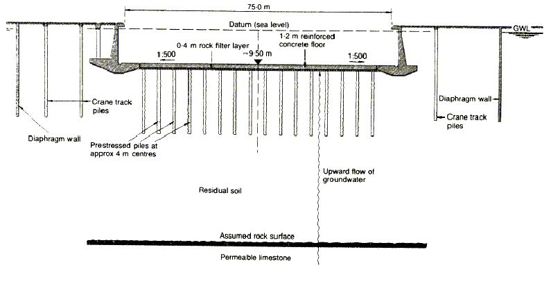
Now we come to the most devastating and unexpected form of corrosion in my experience. To continue the analogy of warfare, this is not so much an ambush as a full-scale surprise attack by the enemy on an undefended flank. To describe it adequately I have to set the scene for you. I mentioned earlier a dry dock that proved very difficult to construct due to the permeability of the soils. This was in Greece in the 1960s and in the 1970s the same client decided to build a further large dry dock (420 m long by 75 m wide by 12 m deep below ground level) in the same shipyard. Perhaps fortunately, he wished to have a design and construct form of contract. The client appointed our firm to draw up the contract documents, check the design and supervise the construction. The contract was won by an Italian consortium who devised a method of dewatering the excavation using bentonite diaphragm walls. Their design exhibited Italian flair and the construction was carried out to a very high standard.
A dry dock, together with its gate, resembles a very large boat which has a tendency to float or be lifted disastrously by the surrounding and underlying ground water. There are three ways of overcoming this: make the dry dock very heavy - typically for such a gravity dry dock the concrete floor would be about 9 metres thick; anchor the floor down to the underlying rock or soil; or drain under the dock floor such that very little hydrostatic pressure can build up. This last solution ceases to be viable in very permeable soils when the amount of pumping, which must be continuous when the dry dock is dry, becomes too great and the cost of the pumping outweighs the saving in capital cost.
The Italians elected to anchor the dock floor using concrete piles constructed from above ground water level, to avoid any differential head and water flow, with tendons cast into them which were prestressed after the excavation had been carried out and the floor had been cast. The cross section is shown below (Figure 1).
|
| Figure 1: Typical cross-section of new No. 5 dry dock as built in 1977 |
All was well until eight years later when, without warning, a large area of the dock floor (approximately 40 m x 30 m) adjacent the side wall lifted and burst releasing a huge quantity of water which quickly flooded the dock. Fortunately, there was no ship in the dock at the time and there was no-one on the dock floor. Our firm was asked to investigate the cause and propose a repair. Initially, it was thought that something had caused an area of piles to fail and lift. A repair was planned to convert the area that had failed into a gravity floor by isolating it with contiguous piles on its perimeter and replacing it with an area of deep concrete. A contractor was appointed who installed a large dewatering system which allowed the damage to be inspected in the dry for the first time. It was discovered that neither the ground nor the piles had lifted but the pre-stressing tendons had failed, in every case, within the depth of the floor slab. In order to establish if the whole failure area would be covered by the proposed repair the anchors in the surrounding areas were examined. To our consternation it was found that even well outside the failure area a number of the strands had failed. In fact, it was random over the whole floor and, presumably, the area that failed happened to reach the critical point first.
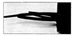
There were 12 seven-wire strands in each pile and each wire had failed with a helical fracture plane, similar to a torsion failure, with no necking to indicate a tension failure. Laboratory examination established the cause as stress corrosion or, as perhaps it is more correctly known, hydrogen embrittlement, which can result in failure of steel when subject to high stress. The strands passed through the concrete floor slab within steel tubes which were filled with epoxy resin as protection. It seems that the resin must have cracked allowing minute quantities of water to enter and, as part of the minute corrosion process, free atomic hydrogen had entered the steel causing hydrogen embrittlement and failure. Now this is really scary in civil engineering. Construction work on this scale is pretty rough stuff and to have a massive failure due to a process involving minute quantities of water and corrosion which is not visible to the naked eye is alarming! Furthermore, the process does not seem to be fully understood even now.
The solution was to convert the main part of the dock into a drained dock although the amount of water and the costs of pumping were high (in the order of 3000 tonnes/hour). A further sobering event was that during the repair, strands outside the failure area continued to fail. A further 14 strands broke during the five months after the initial inspection.
|
| Figure 2: Typical anchor cone with wires attached showing stress corrosion fracture |
|
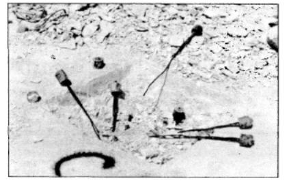
| Figure 3: Typical view of an anchorage excavated to expose anchor cones which could be lifted out by hand with broken wires attached |
This most alarming occurrence is a dramatic example of stress corrosion but it is not exceptional. It has occurred in a number of post-tensioned prestressed bridges where the importance of the seemingly routine grouting up of the ducts after stressing the tendons is now realised to be vital. It has also caused great concern in the oil industry; there was a recent failure of a manifold at BP's Thunder Horse field where extremely low temperatures may have been a contributory factor. In addition, the Nuclear Industry is greatly concerned. The engineering profession really does need to have a better understanding of all this.
So what are the lessons? Civil engineers, involved in design, do have to consider the durability of the structures they are designing at every stage. They do need to understand the corrosion processes and to have an awareness of the more unusual forms.
As a footnote, I would like to add that I consider myself extremely fortunate to have read Engineering Science at the University. It gave me a very broad academic base which enabled me to learn and practise the art of civil engineering, as well as its science, throughout my working life. It has been fascinating and varied, taking me from Argentina to Singapore, often exciting, sometimes exhausting and, at times, demanding to the limits of my capability. I wouldn't have missed it for anything!
Reference: GP Martin and AC Arnold. Failure of dry dock floor in Scaramanga, Greece, resulting from stress corrosion damage to anchor pile tendons. Proceedings of the Institution of Civil Engineers, Dec. 1992
| << Previous article | Contents | Next article >> |
| SOUE News Home |
Copyright © 2007 Society of Oxford University Engineers |
SOUE Home |