| Issue 2 |
In investigating the performance of internal combustion engines, it is obviously helpful if one can see what is happening in the cylinder during the combustion phase. To this end we have built a single-cylinder spark-ignition engine with a window in the piston. A mirror below, aligned at 45°, reflects the light out sideways. The mirror has to lie between the window above and the gudgeon pin below, so a much lengthened piston is used, with a cutaway central portion, so that it can reciprocate up and down around the stationary mirror. See Figure 1. There are windows near the top of the cylinder wall too, but these are necessarily blocked near top dead centre where most of the combustion occurs.
A fully digital CCD camera system is used to grab images once per cycle. This can be used in two ways:
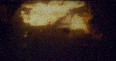
We use not only the natural light from combustion (Fig. 2), but also laser diagnostic techniques, such as Degenerate Four-wave Mixing, developed by Professor Paul Ewart of the Clarendon Laboratory. This can identify temperatures and concentrations of species such as the hydroxyl radical (OH) and nitric oxide (NO).
In parallel with the experimental studies we have developed a multi-zone combustion model that predicts the performance and emissions of spark-ignition engines. It can predict temperature and NO emissions for both homogeneous and stratified-charge combustion. The model is useful both for validating our experimental data (since the model always obeys the laws of conservation and thermodynamics - unlike some experimental data!), and for giving insights into parameters that cannot be measured.
|
| Figure 1 - Engine with optical access |
A particular interest is the combustion performance of pure fuel components (liquid and gaseous), and a recent project has been looking at how soot is formed. The camera produces "R, G and B" signals, and their relative strengths (R/G and R/B) are each a function of the temperature of the soot and of how much of it is present. Thus both the temperature and "loading" of the soot can be determined.
Figure 2 illustrates the use of "soot pyrometry" to study a "pool fire". Pool fires occur in cold engines, when the fuel literally floods the engine. Puddles of fuel form behind the inlet valve and do not fully vaporise; when the inlet valve opens the fuel forms a film on the piston. The vaporised fuel that has already mixed with the air burns first. Subsequently the liquid in the film evaporates and burns with a diffusion flame. There is a wide variation of air/fuel ratios, with very rich mixtures close to the liquid, so the flame is quite sooty. (See Proc. I.Mech.E. Vol. 125 Pt C, pp 1041-1052, 2001 for more on this technique.)
|
| Figure 2a - Natural light image |
|
| Figure 2b - Temperature colour-coded image |
|
| Figure 2c - Soot-loading colour-coded image (brown area is sootiest) |
| << Previous article | Contents | Next article >> |
| SOUE News Home |
Copyright © 2003 Society of Oxford University Engineers |
SOUE Home |