| Issue 11 |
Artificial three-dimensional vision began with Charles Wheatstone, pioneer of the electric telegraph, who invented the "stereoscope" in 1838. By using this instrument to view two photographs of the same scene, taken from slightly different places, one seems to see the scene in 3D. This of course is a static picture. The first 3D moving picture, L'Arivée du Train, was made by the Lumière brothers in 1903. There were various other attempts at different times in the 20th century, but these never caught on, for various reasons. But there has been a strong revival of cinema 3D since 2005, e.g. with the film Avatar in 2009. And many sporting events have been broadcast live in 3D TV, the Arsenal v Manchester United match in January 2010 (the first such in the UK), the FIFA World Cup in the same year, and some Wimbledon matches in 2011. According to Dixons, 20% of televisions sold here are now 3D.
There are many cues to depth which arise from the two-dimensional images on our retinas, e.g. perspective, variation of apparent size with distance, depth of field, relative motion etc. The fact that we have two eyes, typically 60-65 mm apart in adults, offers further clues. When we look at a close object, the eyes turn towards each other ("vergence" is the technical term), and the brain deduces distance from this. And it gets further clues from the fact that the background to a close object will be slightly different for each eye ("stereopsis").
To produce stereoscopic pictures from a single screen, there must be two pictures on it, encoded so that each eye sees only one of them. The viewer has to wear glasses designed to distinguish between them. Some methods that have been used are:
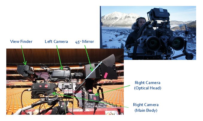
This is independent of how the 3D pictures captured are eventually going to be displayed. Clearly, two cameras are needed, but it is quite difficult to have them as close together as a pair of human eyes, and in any case, for practical filming it is useful to be able to vary the spacing. One also wants to be able to vary the toe-in, i.e. the vergence, and to control the alignment of the two images, and to be able to zoom both cameras accurately together. A useful trick is to use a beam splitter, a semi-transparent mirror at 45° to the line of sight, so that one camera can be in the sight-line and the other above or below, looking vertically. The inter-axial distance (equivalent to eye-spacing) can then be adjusted easily, even to zero if required. It makes for a bulky rig, which loses half the light and is vulnerable to dust on the mirror, but is very useful!
|
| Figure 1: Stereo camera rig |
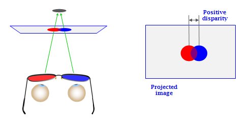
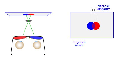
Human eyes automatically focus at the distance appropriate to the vergence, i.e. we focus on what we are looking at. But in artificial 3D, the eyes have to focus on the screen, which is where the images are being generated. But the image may be seen as being behind or in front of the screen, depending on the lateral displacement of the two images (see Figures 2a and 2b below.) So the viewer's eyes have to focus and converge at different distances, not something they naturally do. We can in fact do it, but within limits, which are not the same for each individual. So there have to be limits on the depth of 3D that one attempts to reproduce, and the 3D effect as seen has to be consistent with 2D depth cues. There is evidence that different limits are appropriate for cinema and for TV, the screen sizes and viewer-screen distances being very different in the two cases.
|
| Figure 2a: Positive disparity, where the image appears to be behind the screen |
|
| Figure 2b: Negative disparity, where the image appears to be in front of the screen |
The two cameras should be aligned so that any one object appears at the same height in each eye, though displaced laterally to give the 3D effect. Vertical displacement causes eye-strain, and if large enough destroys the 3D illusion. So the cameras have to be accurately aligned with each other on the rig, and they have to zoom and focus identically, and have matching colour characteristics. In fact, when zooming a typical camera, a point at the centre of the picture at one setting will be somewhere else at another setting, due to imperfections in the lens, and its alignment on the camera. One can modify this a bit by tapping the lens, but this is not really a very good idea. But it can be corrected with servos, or by digital modification of the image. And the cameras have to take their shots in synchronism.
For live broadcasts, all these things have to be right first time. There is no opportunity to "do another take" or "fix it afterwards"!
Sarah explained how her own recent work had been the development of a "Live 3D Correction Box" to handle most of these problems on-line. It uses the same chip-set as Sony's PlayStation 3, suitably adapted for this purpose, and performs the following functions:
The equipment had been used at the FIFA World Cup in 2010, and at Wimbledon in 2011. Extracts from the films shot there were shown continuously in the foyer on a large 3D television, using the circular-polarisation method.
|
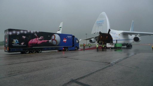
| Figure 3: A Russian Antonov transporter plane, used to ship two 3D-equipped outside broadcast trucks to South Africa - the only aircraft big enough to do the job |
| << Previous article | Contents | Next article >> |
| SOUE News Home |
Copyright © 2013 Society of Oxford University Engineers |
SOUE Home |