| Issue 7 |
Martin started by saying that his task was to describe the work of about 200 people over 38 years, so he would not be able to go into very great detail. They had designed and built a whole series of innovative wind tunnels, mostly short-duration ones, and instrumentation for measuring heat transfer, mainly directed at the cooling of gas turbine blades, and had had a remarkable record of success, of significant benefit to the aircraft-engine industry.
To see why the topic was so important, we were invited to compare the 1938 Whittle single-shaft jet engine, uncooled and not very efficient, with a recent Rolls-Royce Trent three-shaft machine, which achieves a thermodynamic efficiency of over 50% by raising the gas temperature to 1800 K. But the maximum temperature that the first-stage turbine blades can stand is 1200 K, and they would melt in a gas stream at 1800 K were they not cooled by an internally supplied flow of cooling air at 800 K, supplied from the compressor. 800 K is hardly "cool", but it is well below the required blade temperature.
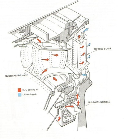
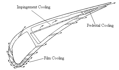
So it is necessary to maximise heat transfer from the blade to the coolant, and minimise it to the blade from the combustor gas, and this leads to a very complex blade structure. Air not only cools the blade on its internal surfaces, but is also fed through bleed holes into the external boundary layer (film cooling), thereby reducing heat flow from the outside (Figure 1).
|
| Figure 1: Cooling air flow in a high pressure turbine |
The founding of the Oxford group can be traced back to Douglas Holder who, from a background of hypersonics at the National Physical Laboratory, came here to be Head of Department from 1961 until his untimely death in 1977. He brought Don Schultz with him, and the two realised that the shock-tube techniques developed for high-speed aerodynamic research could easily be applied to study flow over turbine blades. It was Don Schultz and Terry Jones, a physicist by background, who with Holder's encouragement actually started the group in 1968, and by 1973 there were 12 people in it. Martin himself had joined in 1973-4, having originally come here, with an electrical engineering background, to do a DPhil in plasma physics.
It was clear by then that the work was going to need a lot more space than could be found on the Keble Road triangle. As it happened, Oxford's electricity generating station, originally built in 1897 down by the river at Osney, was finally abandoned as obsolete in 1969, and Holder persuaded the University to buy the building in 1974. It took a lot of work to adapt it for its new use, not least because thermal power stations are designed to lose heat, and this one did, very effectively in winter!
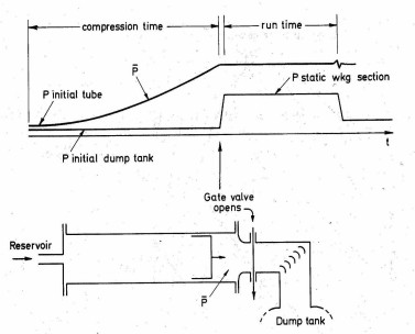
The first tunnel to be installed there was the "isentropic light piston tunnel", conceived by Terry Jones, in which a volume of air is first compressed isentropically by a fast-moving piston, driven by a compressed-air supply applied to the other side. A valve then opens and the hot air flows over a cascade of blades and down into a dump tank, giving a uniform flow for about 0.1-0.4 seconds (see Figure 2). Martin built the amplifiers for the instrumentation, and the data was recorded by a PDP11 computer, running off two floppy discs. The experiment was simulating the flow of gas at 1800 K over blades at 1100 K, but this could be done adequately with a flow of air at 450 K over blades at room temperature, 300 K, giving the same ratio of absolute temperatures, provided the Reynolds and Mach Numbers also matched.
|
| Figure 2: Isentropic Light Piston Tunnel, invented by Terry Jones in 1970 |
But with this apparatus they would be simulating a steady flow, whereas in the real turbine the rotor blades are sweeping past a row of stator blades, which introduces all manner of transients: shock waves, blade wakes etc. The cascade of turbine blades in the tunnel was stationary, but the transients could be generated by sweeping a series of wires across the upstream flow, mounted radially on a disc rotating at 20,000 rpm. They learnt much about the nature of the transient flows that resulted.
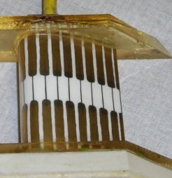
The heat transfer instrumentation was based on platinum film resistance gauges (Figure 3), painted and fired, pottery-fashion, on to blades of Macor, a machinable glass ceramic (and therefore an electrical insulator). The heat transfer to the blade can be deduced from the temperature rise history indicated by the gauges as the hot air flows past them in the 0.4 second run.
|
| Figure 3: Thin film heat transfer gauges: early Macor blade (left), later 3-D blade (right) |
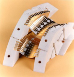
The next stage was to put an actual turbine rotor into the tunnel. This was a joint project between Don Schultz and Roger Ainsworth, who had originally graduated from Oxford, and then returned after periods at Rolls-Royce and Harwell. In its brief test run the rotor accelerated from 6000 to 9500 rpm. The blades for it had to be of metal, to withstand the stresses, so the platinum gauges were sputtered on to insulating Kapton film, which was then wrapped around the blades. This was capable of withstanding accelerations of 6000 g. The electrical signals were brought out through slip-rings, but had to be electronically buffered first, and the electronics too had to capable of withstanding the accelerations. They put semiconductor pressure gauges on the rig too, to study the aerodynamics. They were particularly interested in measuring what happened between the blade tips and the surrounding casing.
The group was then asked to build a significantly larger such tunnel, of 1.2 m diameter, for the National Gas Turbine Establishment at Pyestock (now part of QinetiQ). Originally this just had a stator, but a rotor was added in 1991, capable of 10,000 rpm, with a patented "Turbobrake" to hold its speed constant. The "run time" was 0.4 s.
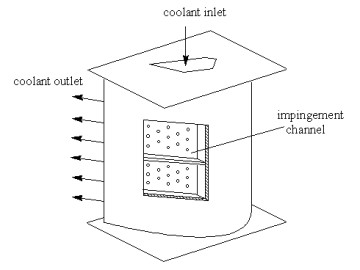
The above work all concerned heat transfer from the external gas to the blades. Studies of the internal cooling processes were begun by Terry Jones in 1983, and continued by Peter Ireland, who has now left to join Rolls-Royce, and by David Gillespie, to whom Martin was indebted for information on the work. Terry adopted "thermochromic" liquid crystals for this purpose. These change colour at known temperatures. A combination of two or more types, with different transition temperatures, and some complicated data-processing, permitted heat-transfer rates to be deduced from relatively cheap experiments. In the blade itself, cooling air is fed to the interior, and some is directed perpendicularly on to internal surfaces, or on to "pedestals" between surfaces, cooling them by "impingement". The rest is bled into the external boundary layer, thus cooling it and reducing heat transfer there (Figure 4). The photochromic crystals are particularly useful for studying impingement cooling, using specially designed rigs (since one can hardly film what is going on inside a blade).
|
| Figure 4: Turbine vane cooling |
A recent line of research had been directed to the cooling of the blade leading edge by a pattern of intersecting bleed holes, but the details of this were still confidential.
A rather different line of work at about this time concerned flight tests of the external flow around an engine nacelle, to see what could be discovered about the laminar-to-turbulent transition. Film resistance thermometers were used again, since turbulent flow produces temperature fluctuations. The tests were done on a Fokker VFW614 airliner, a convenient aircraft for the purpose since the nacelles are above the wing and visible from the cabin windows. The Oxford group went on many successful test flights and were encouraged to learn that the laminar boundary layer seemed quite robust against engine vibration and noise.
Another tunnel, built in 1982, was the "blowdown tunnel", with which certain aerodynamic tests could be done much more cheaply than with a continuously operated tunnel needing many megawatts to run it. In 1990 Gary Lock and Shengmin Guo put an annular cascade of 36 nozzle guide vanes into it, to do both aerodynamic and heat transfer tests at the same time. The blades were heated but the gases were at room temperature. To get the correct density ratio between coolant and mainstream gas, he used a mixture of sulphur hexafluoride and argon for the former, an option now closed off because of the "greenhouse gas" properties of SF6. Reynolds and Mach Numbers matched those of the engine, but the tunnel used 38 kg/s of air at 2 bar and room temperature whereas the engine being simulated used 120 kg/s at 32 bar and 1750 K.
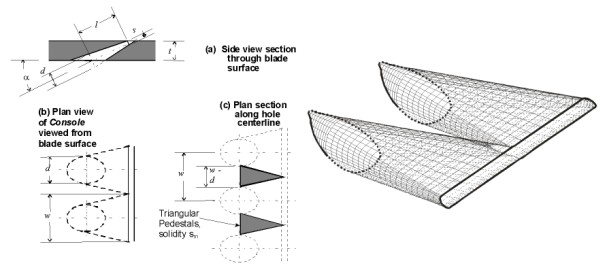
An interesting development in 1998 led to a patent for a new shape of bleed hole, called a "console" (converging slot hole), which starts with a circular cross-section on the inside of the blade, but changes to a narrow slot at the outside, reducing in cross-sectional area on the way. A row of such holes looks like a continuous slot on the outside, but still leaves enough metal on the inside to preserve the structural integrity of the blade. The wall of the "console" is made up of a family of straight lines, so it can be drilled by a laser. The coolant leaves the blade in a single sheet rather than in numerous separated jets, as happens with cylindrical holes, which leads to a significant improvement in the cooling of the external surface. (See Figure 5.)
|
| Figure 5: Console cooling holes |
Another topic of interest was the study of leakage past the tips of rotor blades. The tip clearance on a real engine is so small that it is difficult to measure what happens there, but the large low-speed "architectural" wind tunnel used for many years by Colin Wood became available on his retirement in 2003 and gave an opportunity to scale the whole thing up enormously - the "largest turbine cascade in the world". The cascade was 4 m long with a blade chord of 1 m, and the tip clearance became 30 mm. Gas velocities there were measured by correlation between successive photographs of particles in the flow, and heat transfer at the tip by heating it electrically, and observing temperature with an infra-red camera inside the blade.
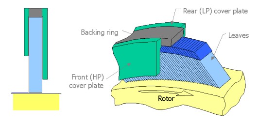
There are many places in a turbine where the need to allow for thermal expansion means that there are annular gaps between stationary and rotating parts where axial leakage can take place, with resulting loss of efficiency. The classic way to reduce such leakage is the "labyrinth seal", but it can almost certainly be improved on. The first attempt by the group was the "brush seal", in which the space is filled with thin wires, attached to one part and sliding over the other, rather like a brush. This makes for a much more tortuous gas path, but has some weaknesses. Better is the "leaf seal", in which the bristles of the brush are replaced by leaves, long in the axial direction but thin tangentially. This arrangement, it appears, may not only have a very long life, but also very little friction, since the presence of the gas causes the leaves to ride just clear of the rotor surface. (See Figure 6.)
|
| Figure 6: The leaf seal |
Other topics touched on were Tom Povey's mass-flow measurement system, and his supersonic cascade ("the smallest turbine cascade in the world"); and his "annular sector facility" which uses a "de-swirl" element to get a good representation of a complete blade ring with just a short six-bladed sector. There was Peter Ireland's work on lightweight air-to-air heat exchangers; and Alex Matthews' work using the hypersonic gun-tunnel to study scramjets and also the potentially disastrous consequences of a combustion-chamber burn-through.
Martin went on to acknowledge their debt to the group's sponsors, primarily Rolls-Royce of course but including many others; to list some of the honours and awards received over the years; to say what he thought were the main contributory elements of their successes (Table 1); and finally to offer the group and its new leader, Phil Ligrani, his best wishes for the future in their new home in the Axis Point building.
| |
| Table 1: Recipe for success |
| << Previous article | Contents | Next article >> |
| SOUE News Home |
Copyright © 2008 Society of Oxford University Engineers |
SOUE Home |