| Issue 5 |
My father would tell you that my interest in telecommunications began when I was a teenager and spent many a day holed up in my bedroom with the phone glued to my ear; this is not strictly true. During my days of studying at Balliol (1995-9) I was fortunate enough to receive a sponsorship from the company formerly known as Cable & Wireless Marine and due to this involvement I started to develop an interest in fibre optics and its use in telecommunications. Hence after I went down I sought out a career in submarine systems engineering. And what amazed me then, and still continues to amaze me, is the lack of general knowledge that exists regarding this fascinating field which we the Internet generation have come to be so dependent upon. For example, if I ask you 'what is the first thing that comes into your head when I say the word telecommunications', what would you say? Perhaps those of an older generation would mention copper cables and analogue signals, youngsters could probably list a number of applications and wax lyrical about the benefits of Voice Over IP. But if you ask anyone in the industry you could get any number of answers ranging from the complexities of sub bottom profiling to the latest Forward Error Correction code developed to aid transmission. 'Qué?' I hear you cry, and thus my aim to enlighten.
Fibre optics have been used in submarine systems since the late 1980s and such systems are installed worldwide for the purpose of carrying telecommunications traffic both nationally and internationally. 'Popular' routes such as the Atlantic can be home to over ten operational fibre optic cable systems. This may not sound like many but when you consider that each system costs hundreds of millions of dollars to install you begin to understand the scale of the business. Furthermore if you consider that upwards of 100 million simultaneous telephone calls can be made down an individual cable, which in deep waters are typically 17 mm in diameter, the fibres within which will have a diameter of around 245 µm, you can only imagine the technology progression in the last 15 years.
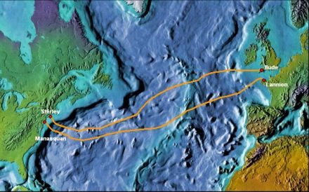
As a case study I would like to consider the example of the Apollo Submarine Cable System, currently the most advanced of the transatlantic systems. Apollo was built in 2003 and consists of two legs, a Northern cable route (UK-US) and a Southern cable route (France-US), shown in Figure 1.
|
| Figure 1: Apollo Submarine System |
Each cable route constitutes four fibre pairs (a pair is made up of a transmit and receive fibre), with each fibre capable of carrying 80 channels of 10 Gbit/s traffic, giving a 3.2 Terabit/s capability per leg. The equipment used to transmit and receive the signal is known as Submarine Line Terminating Equipment, SLTE, and in the case of Apollo the SLTE transmits the 10 Gbit/s channels with 50 GHz spacing. That means that adjacent channels are 0.4 nm apart, phenomenal stuff.
The mechanical aspects of submarine systems are equally as impressive. The cable has to be designed such that it is capable of protecting the fibres during installation and once on the seabed. External aggression is made up from many factors, fishing gear and ships anchors being the main culprits. Historical studies show that in the North Atlantic, for example, over 50% of external aggression faults in cable systems are caused by fishing, hence, as you can imagine the relationship between the telecommunications industry and the fishermen is one which needs constant maintaining. Additionally there is natural aggression from landslips, earthquakes and sand waves exposing areas of burial. Subsequently submarine cable is designed with high tensile strength steel wires protecting the polyethylene insulating layer that encases the fibre core. In the case of Apollo a specially designed cable was deployed with improved crush resistance to withstand impact with fishing gear and other such obstacles.
Marine activities typically commence with a Desk Top Study, which is a paperwork exercise to review a proposed cable route. One of the key issues to be addressed early on in a project is to select a landing site. Landing sites need to be in areas where it will be easy to protect the cable, straightforward to pull it on to the beach, with good proximity to an area which could house a cable station (where the equipment will be installed) and it is unlikely that there will be a lot of external aggression: such as a beach. Not surprisingly the tourist boards of coastal towns are none too keen on their beaches being taken over by a bunch of hairy engineers and their noisy toys, which rules out the summer months for any landings. A further area that causes constraint is that of permits and licences. Many a project has been delayed due to the permitting process and its requirements. The protection of rare and often obscure plants and animals, the bog turtle being a prime example, has cost telecom owners a pretty penny or two.
Following this study a survey is carried out to refine the proposed route and determine how much burial will be required, and is possible. The survey results will provide a map of the contours of the seabed and details of its geology. All this data is used to determine the route of the cable. The cable should be laid such that it follows the contours of the seabed, hence enough slack must be built into the system such that there are no suspensions; if you can imagine the cable suspended between two bodies such as rocks, as the cable moves and sways due to transverse currents it will rub at the contact points causing abrasive damage. In shallow waters or areas of danger the cable should be buried as much as possible. Burial is typically performed using a plough (hybrid of the agricultural plough) towed from a winch on the back of a ship. Burial depths are typically around 0.6 m, with further burial possible, and necessary, in soft silty areas. Ploughing is a careful and slow process that calls for vessel speeds as slow as 0.5 knots.
Marine installation operations are often split into shore end works and the main lay, depending on how easy it is to get the installation vessel close to the beach. The completion of shore end operations is also a complex process: the cable is floated with buoys and then attached to a pulling line, which in turn is attached typically to a JCB on the beach. Once the cable has been pulled into place divers will swim out and cut off the buoys and then guide the cable into its seabed position. For the near shore areas that are sandy, divers will use jetting tools to bury the cable.
After this operation is complete, the main lay will commence with plough burial up to 1000-1500 m water depths, obviously dependant on how much burial is possible. After the plough's work is complete the cable will be directly paid out of the ship with the necessary slack, determined during the survey, at speeds of around 4 knots. In the case of Apollo the Northern link is approximately 6200 km and the Southern route is slightly longer at 6500 km. Marine operations lasted approximately six months. It is worth noting that much of the enjoyment factor when working on marine operations is based on i) what time of year the marine operation is being performed and ii) what part of the world the operation is taking place. I myself have been fortunate having spent three months in the Pacific installing the first fibre optic link between Fiji and Hawaii. Unfortunately shortly after completing our shore end works a military coup broke out in Fiji and for a while the only communication out of the island was coming through the cable we were actually laying.
Another key factor of modern fibre optic systems that we have not touched on is optical amplifiers. As channels traverse through the fibre optic core their power is attenuated and subsequently there is a requirement to amplify the signal at regular intervals, typically around 50 km. Historically it was necessary to turn the signal back to its electrical form, perform the amplification and then convert back to the optical domain, all done using a large and cumbersome piece of equipment known as a regenerator. Luckily a bright spark discovered that by exciting doped Erbium fibre (Er3+) it was possible to amplify the signal in its optical state, thus developing the optical amplifier or repeater. As you can imagine this was a fantastic advancement as the less electronics that you have on the seabed the better. Think of how much you grumble when you have to return something to Currys, now imagine chartering a vessel to sail 2000 km out to sea to pick up a repeater from 5000 m depth of water in order to fix a widget - best avoided at all costs.
Unfortunately my time is up before I can enlighten you on the impressive progress in SLTEs and other terminal equipment. There are now Forward Error Correction codes that far exceed standard Reed Solomon codes, allowing for a larger number of errors to be corrected on each channel and hence give extra margin to the Power Budget of a system. Developments in fibre properties have allowed higher output powers to be transmitted from terminal equipment without the onslaught of non-linear effects. Transponder cards are now manufactured to be fully tuneable across a range of channels, allowing operators to key in a required wavelength and the lasers within the transponder will immediately shift across the band. Only when we think that as recently ten years ago cables were carrying 140 Mbit/s over one channel can we truly appreciate the advances in this industry. I look forward to the next ten years.
|
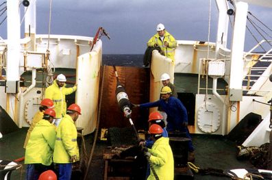
| Figure 2: Deployment of a Repeater |
| << Previous article | Contents | Next article >> |
| SOUE News Home |
Copyright © 2006 Society of Oxford University Engineers |
SOUE Home |