| Issue 10 |
Peter Raynes started by reflecting that when, 40 years ago, he told people that he was working on liquid crystals, he usually got the reply "What are they?" The answer now was more likely to be "Is there any research left to do in them?"
He went on to see if the audience had any idea of the history of the subject. Not very much apparently, but the questions, and the answers to them, were:
A liquid crystal is in fact a state of matter intermediate between a solid and a liquid. In a crystalline solid, the molecules (assumed to be long and thin) are in definite positions and all oriented, for example they could be exactly parallel. In a liquid the positions and orientation are random. In a liquid crystal the molecules are randomly positioned, but are partially, but not completely, lined up, and the liquid becomes anisotropic. We were shown, as analogies, first a photograph of scores of logs floating in a Canadian river, which had collected in several parallel groups; and second, a demonstration of rice grains shaken in a dish, which behaved in much the same way. There are liquid crystals in our bodies, for instance in cell walls. DNA in solution forms a liquid crystal, and the high-strength material Kevlar goes through a liquid crystal stage in its manufacture, aligning the molecules. Liquid crystal molecules can line up in various ways, as indicated by the names "cholesteric", "nematic" and "smectic".
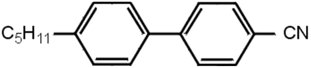
Liquid crystal molecules are usually organic, and of modest size. Those used in displays typically contain a couple of benzene rings, with attachments, e.g. as in Figure 1.
|
| Figure 1 |
They show a liquid crystal phase over only a fairly narrow range of temperature, and the lecturer showed us a bottle containing a substance of milk-like appearance, which was in fact a liquid crystal. But when warmed a little it became completely clear, showing its change to normal liquid form.
Why are liquid crystals so useful? They have three properties, all derived from their anisotropy:
If the applied electric field is perpendicular to the surface, effects 2 and 3 can act in opposition, and it takes only a small electric field to dominate. With no field, the molecules lie parallel to the surface and along the preferred direction given to it by rubbing. But when an electric field is applied, they rotate so as to be parallel to the field and perpendicular to the surface. This effect was first discovered in 1932 by Freedericksz (who regrettably died a few years later in one of Stalin's Siberian forced-labour camps).
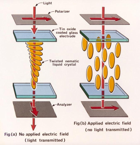
The "Twisted Nematic" LCD, based on this effect, was invented by Schadt and Helfrich in 1971 (Figure 2).
|
| Figure 2 |
The lecturer made a simple display for us in the lecture room. He took two glass plates, coated in indium-tin oxide to make them electrically conducting, and rubbed them to impart the directional property. He put them one above the other, with a small gap between, and their preferred directions oriented at 90° to each other. A small amount of liquid crystal was then injected between them. The result was that the molecules lined up parallel to the preferred directions at top and bottom, but changed gradually from one to the other, i.e. by 90°, as one went from top to bottom (the "twisted nematic"). This had the effect of rotating by 90° the plane of any wavelength polarised light passing through it.
Polarising sheets were then placed above and below, each with its polarising direction parallel to the rubbed direction of the neighbouring glass. The whole assembly was set up on an overhead projector, and thus illuminated from above. Over most of the area, the crossed polarisers prevented any light transmission, but some did get through where the liquid crystal was, since it rotated the plane of polarisation.
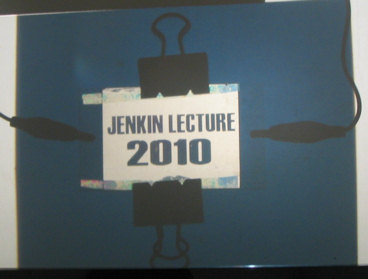
He then applied a voltage between the electrodes on the top and bottom plates. Typically only 2 V is needed, and this rotated the molecules to lie normal to the surfaces, so their ability to rotate the plane of polarisation disappeared. Thus the electrified area became opaque, showing the text 'Jenkin Lecture 2010', while the rest remained transparent (Figure 3).
|
| Figure 3 |
There is an interesting story about how the UK got involved in LCD development. The Royal Radar Establishment (RRE) in Malvern had in the 1960s been transferred from the Ministry of Defence to the Ministry of Technology. They were visited in 1967 by the then Minister of Technology, who boasted about the sums his Department was spending on the development of Concorde. The Director pointed out to him that even larger sums were being paid as royalties for the use of overseas patents relating to colour cathode-ray tubes for television receivers. The Minister's response was to direct RRE to institute research on alternative displays, and in 1970 a group was set up to do this; the lecturer joined this group in 1971. Who was the Minister who had authorised this? It was in fact John Stonehouse, who later became notorious for faking his own death by drowning so that he could go and live with his mistress in Australia under another name.
In 1970, all known liquid crystals were most unsuitable for displays. They were chemically unstable and decomposed; they were coloured; and they had poor switching characteristics. George Gray and Ken Harrison in the Department of Chemistry at Hull University were given a research contract by RRE to see if they could make something better, and they did. They realised the faults were attributable to chemical groups between the benzene rings, disappearing in compounds without them, and came up with the cyanobiphenyl compounds, one of which is shown in Figure 1. However this one on its own works over too narrow a temperature range (22-35 °C). An alternative with C8H17O at the left-hand side works over 54-80 °C, but a eutectic mixture of the two covers 5-50 °C. By combining four different compounds in quite precise proportions, the lecturer formulated a mixture, given the name E7, which was usable over -10 to 60 °C, and was perfectly satisfactory for most applications. The performance and stability shown by E7 allowed the LCD market to grow rapidly and to dominate quickly the small portable display market; E7 dominated the liquid crystal market for more than 10 years.
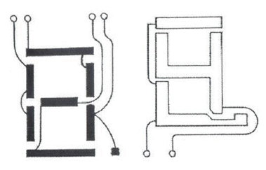
At this point we had a display very suitable for small scale applications such as watches and calculators, where only a modest amount of information was to be displayed. The difficulty in displaying more information, for a computer or TV, is that the number of electrical connections between the display and the drive electronics becomes unmanageable. Each element in e.g. a seven-bar number display plus an associated decimal point needs its own lead, and the back-plane needs another; total nine. A ten-digit calculator display (with a common back-plane) thus needs 81 leads. By dividing the back-plane into two sections, and feeding the digit elements in pairs (Figure 4), we can get down to six connections per digit. But this relies on the bars being OFF with say 1 V between the electrodes, and ON with 2 V (which the twisted nematic display can just do). This "multiplexing" technique was quickly adopted for products such as calculators to reduce the number of connections between the display and the drive electronics. It was realised that it could, in principle, be extended further, but only if the voltage ratio between the ON and OFF segments could be reduced significantly below 2.0 and as close to 1.0 as possible.
|
| Figure 4 |
A computer or TV display has around 106 elements, and has a matrix of electrodes of around 1000 rows and 1000 columns and it was realised that for these displays, a breakthrough was needed.
There followed two independent breakthroughs involving the RSRE (as the RRE had now become). The first was the development around 1980 of amorphous silicon thin-film transistors (TFTs) by RSRE and Walter Spear and Peter LeComber of the Department of Physics at Dundee University. These immediately removed any restrictions imposed by the LCD switching, but only worked on a laboratory scale. The prospect of very high development costs, and no certain market, discouraged industry from taking up the technology. Fortunately, in 1982 the lecturer, working with Colin Waters, discovered that increasing the "twist" in the twisted nematic, from the 90° as described above, to 180° or 270°, made the ON/OFF transition much steeper (Figure 5) and considerably improved the ability to "multiplex" an LCD. This effect became known as the Supertwist display and was used in early laptops and mobile phones, and is still found in card readers, car radios and a host of domestic and office equipment.
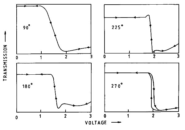
|
| Figure 5 |
The availability of an LCD display suitable for laptops and mobile phones developed the market for these products and encouraged the display industry to invest in the development of thin-film transistors and their incorporation into displays at an acceptable price. After some 10 years of development TFT/Twisted Nematic LCD displays became a practical reality and gradually replaced Supertwist displays in laptops and mobile phones.
In contrast to a laptop display, a TV display also needs: high contrast; fast switching; and a wide viewing angle, which Twisted Nematic technology was unable to achieve. Two alternative LCD modes, both using TFT arrays, have been more successful:
In the latter the electric field is parallel to the screen, and switched on and off by the thin-film transistors. A colour picture is achieved by having three pixels for each picture element, passing white light through red, green and blue filters respectively. Numerous additional layers are required to make a satisfactory display, e.g. to generate a uniform back light behind, and to enhance contrast, improve viewing angle, suppress reflections and protect from damage.
LCDs are now in their tenth generation, and are made in enormous sheets greater than 3 m by 3 m, to be divided up as required. The total thickness is 1 mm, of which the LC layer is only 5 µm thick, with a tolerance of 0.1 µm. That this tolerance can be maintained over 3 m x 3 m is truly remarkable.
There is still room for further progress. For instance instead of passing white light through colour filters, one could generate it with coloured LEDs shining alternately through the same pixel, thus saving two-thirds of the energy. Or displays could go back to using reflected light. They could be made reflective and bistable, so that they would emit the same text etc. continuously after being set up, thus using no back-light energy and very little for the drive.
There are of course other forms of flat display. Electrophoretics, used in e-books, display only black and white images. Plasma displays seem to have life problems. Organic LEDs are on their way, and are now in mobile phones at least. The lecturer was not convinced they would be used for larger area displays, but did think they had useful prospects for room lighting.
After the lecture, a lively question-and-answer session ensued. It transpired that the surface modification of glass by rubbing it was not in fact a change in the glass, but in a thin plastic coating on it, which seems more plausible. A number of questions were asked about the failure of European and American companies to commercialise LCDs when they looked like an obvious winner. Some questions were asked about the royalty stream into the UK as a result of the UK's LCD activities: the answer was that these were considerable, but not quite Concorde-sized sums!
| Contents | Next article >> |
| SOUE News Home |
Copyright © 2011 Society of Oxford University Engineers |
SOUE Home |