| Issue 7 |
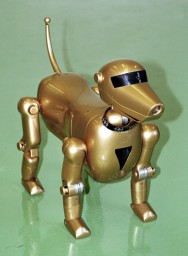
Those with a good memory may recall a small media flurry in early 2001 concerning a large British robotic dog called RoboDog, which featured in various newspapers and TV news programmes, and even had a star turn on Richard and Judy.
Although the media mostly concerned themselves with RoboDog's striking appearance and assorted tricks (headstands, playing football, reading e-mails etc.), it was really intended to be a technology demonstration for a fledgling British engineering company that was interested in using the materials and techniques common in motorsport in a different arena, namely robotic devices.
|
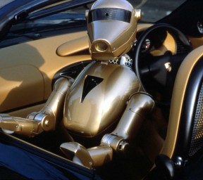
| Figure 1: The RoboScience RS-01 RoboDog (in car, right, for scale) |
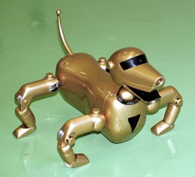
RoboScience was set up by Nick Wirth, the former Simtek Formula 1 team owner and Benetton F1 chief designer, who was looking for a new challenge during a sabbatical from the topsy-turvy and insular world of motor racing. He had long been interested in robotics, and after becoming intrigued by the Sony Aibo robotic dog (an expensive and technologically impressive toy, around 20 cm tall), decided that making a much larger version - roughly the size of a real Labrador dog - would be a good media-friendly way to show off the possibilities offered by the use of modern materials (carbon fibre composites, Kevlar etc.) and design techniques in robotics. The idea for the RS-01 RoboDog was born.
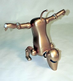
The engineering challenges of making large quadrupeds are significant: weight increases with size cubed, which with longer legs means that the motor torques required at the joints increase quartically. The Aibo weighs 1.5 kg: using traditional materials to produce something the size of RoboDog (around 70 cm) would have produced a robot weighing over 30 kg, which would have had prohibitive power requirements. By contrast, RoboDog only weighed 12 kg, making it able to operate for a couple of hours between recharges, as well as performing its popular "tricks" (headstands and press-ups with a five-year-old child on its back, which both require enormous amounts of power).
RoboDog was created in a remarkably short time - just seven months from conception to having a walking robot - by a small distributed team of people specialising in particular areas of the project, collaborating across three counties via the Internet. The author's involvement was with computing and control, which is the main focus of this article: to attempt to describe the entire project would require rather more pages than are available!
RoboDog's light weight came from a combination of factors: a monocoque exoskeleton made from carbon fibre and Kevlar provided a chassis that was extremely light and strong; the leg joints (which were subsequently patented) combined hinge, gearbox and motor in a single unit that was both small and lightweight (albeit somewhat noisy in the prototype form that appeared in RoboDog), and capable of sustaining high torque for a considerable time; and the electrical system was highly efficient, combining modern battery technology with minimal power requirements to keep the weight down as much as possible. The batteries were mounted in the lower half of the body, to keep the centre of gravity low; the area above this was where all the electronics, computers, peripheral boards etc. were mounted, with cables running through the hollow legs or the middle of the neck tube.
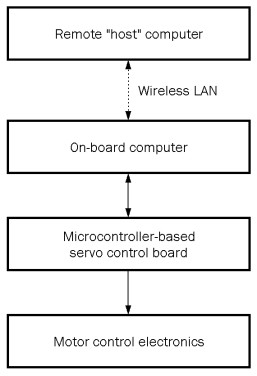
To fit in with the low-power requirement, the power electronics and on-board computers needed to be highly efficient. An early decision was made to use standard systems and interfaces as much as possible, to avoid reinventing the wheel, and for the high-level control software to run on a separate computer, communicating with the robot's on-board systems wirelessly.
The on-board power electronics controlled the high-torque (and high-current) 24 V DC joint motors to position the limbs, each motor/electronics combination forming a distributed position-control servo system. The electronics were designed in-house, but with a control interface that mimicked the pulse-driven interface of standard radio-control servos1. This had two immediate benefits:
However, it was found that the 50 Hz frequency of the incoming servo control PWM signal produced an unpleasant buzzing sound from the motors, so the final version of the electronics put the incoming pulses through a sample-and-hold circuit, from which hardware PID control was used to produce a 25 kHz PWM output signal, fed to the motors via a full-bridge FET driver.
Power for the robot came from 44 Sanyo Twicell NiMH cells, arranged in two parallel arms of 22 series cells, giving a 27 V battery with 7000 mAh capacity (and a maximum discharge rate of 21 A - around 570 W - when needed!)
|
| Figure 2: Block diagram of RoboDog's control scheme |
With the Sony Aibo already well known (as well as having been the inspiration for the project), it was decided that RoboDog should offer Aibo-like functionality to provide high-tech appeal; but the tight timescale and small budget meant that this would have to be done as simply as possible, using off-the-shelf equipment and tools whenever available (rather than doing things from first principles), while retaining intellectual property rights.
The system specification was as follows:
In addition to the real-time software, a computer simulation of the robot's kinematics was also written to allow gait and pose design and analysis (i.e. to work out which servos needed to move where, and when, to allow the dog to walk, sit down etc.). Motion was achieved while remaining statically stable, by keeping three feet on the ground at all times, with the centre of gravity lying within the triangle thus formed; the fourth leg was then repositioned to form another triangle, then one or more of the currently-supporting legs was moved until the centre of gravity crossed the boundary into the new triangle, at which point the robot would fall into the new stable position and the cycle could start again. High-speed motion was statically unstable, relying on momentum to keep the robot moving in the desired direction without falling over.
The software was used to define "motion sequences": lists of joint angles that were needed at particular times to achieve the desired motion. These were processed by the dog's on-board computer, and could be either used alone, or used consecutively to achieve more complex movements from simple building blocks. (If the starting pose of a sequence did not match the finishing pose of the previous one, a smooth transition was automatically made between them.)
RoboDog was a walking Windows 98 PC (strictly, Windows 98 Second Edition, which was the first to support USB devices properly). This platform was chosen because of its familiarity, ease of interacting with external hardware (e.g. USB devices and wireless network cards), and the availability of commercial software packages to provide additional functionality; also, all the software could be developed and tested on existing PCs. There were some concerns: Windows is not known for being a real-time software platform! The version running on RoboDog was stripped down to only those parts absolutely necessary for its operation, and actually proved quite capable of controlling the robot without significant hiccups, provided that the main control software was the only task running.
As has already been mentioned, the on-board computer needed to be small, lightweight and with minimal power requirements. A PC/104 format system was used (about 10 cm square and 4 cm deep, with two linked boards): this operated from a 5 V power supply and consumed only around 10 W when running, providing a modest amount of computing power (a 266 MHz Pentium processor with 64 MB of RAM) and all the necessary input/output connections (serial, USB, a PC card slot and audio). It communicated with the external host PC (whose job it was to do the high-level control) over an 11 Mbps wireless network, using the TCP/IP protocol on which the Internet runs.
The necessary sensor inputs were all achieved using off-the-peg commercial hardware:
Speech synthesis was provided by an inexpensive "shareware" Windows program, which would read out any provided text using the computer's soundcard. Connected to a loudspeaker mounted in the chest, this gave RoboDog a pleasingly deep and appropriately artificial-sounding voice; opening and closing the jaw at the start and end of the speech produced a convincing effect. One minor issue was the software's tendency to recognise the abbreviations for American states, meaning that instances of "OK" in the text had to be changed to "okay" to prevent them being read as "Oklahoma"!
The main requirement for the low-level control software was, of course, controlling the 16 servos in the robot: three on each leg (shoulder/hip rotation in two axes, plus elbow/knee rotation); fore and aft movement of the neck; left/right panning of the head; opening and closing the mouth; and of course wagging the tail left and right! The twelve leg servos and the neck were actually the RoboScience-designed power electronics units appearing to be servos; the head rotation, jaw and tail used conventional radio-control servos.
Servo control initially appeared to be straightforward: a commercial microcontroller board was purchased that claimed to control 16 servos simultaneously, and provide eight inputs of analogue-to-digital conversion (ADC), using a simple system of single-byte commands and responses over an RS-232 serial connection to the main computer. The level of control over the servos was excellent: for each servo, one could define speed and acceleration and a position, and the microcontroller would then send an appropriate sequence of pulses to the servo to make it move smoothly from its current position to the new target, accelerating up to the defined speed and decelerating again at the other end. When the movement was complete, the system would send a response back to the main computer to tell it that the servo had reached its target.
Sadly, although apparently well regarded in the hobby robotics world, this system turned out to be unable to live up to its impressive specifications: it became erratic when used even moderately hard, with servos jumping instead of moving smoothly, end-of-motion trigger events failing to happen, ADC readings failing to occur or being mixed up etc. By the time this became apparent, and investigation had shown that the fault was endemic rather a problem with our particular board, the development of the control software was well advanced and the design required the level of control that the board had claimed.
After further research failed to turn up any other products with equivalent specifications, there was no alternative but to produce a replacement in-house; fortunately an acquaintance was an experienced embedded software engineer, who took a basic commercial microcontroller board and produced a system capable of controlling eight servos in the desired manner, using exactly the same serial command bytes as the unreliable commercial system. Using two of these new boards provided a properly working drop-in replacement for the original system, requiring almost no software changes, with the added benefits of providing 16 channels of ADC instead of the original eight, and the ability to handle the serial communications with the compass, reporting its readings as a virtual analogue voltage. This relieved the PC from having to communicate directly with the compass, and the additional ADC meant that the full range of outputs from the voice activation unit could be used as well as the sonar, accelerometers etc.
A robot is not much use without higher-level control telling it what to do. RoboDog on its own could only start up, boot into Windows 98 and sit there waiting for a connection to be made to it over the wireless LAN, very much like an Internet mail or web server - in fact its communication protocols were designed along the same lines as the Internet protocols HTTP, FTP, SMTP etc., being largely text-based so that a human could log in and command the robot without needing any special software; this was very useful during the development phase.
If a connection was made, the robot's servo control could be activated, individual joints could be moved to arbitrary positions, and motion sequences (produced by the kinematics software described above) could be loaded and processed - by moving the servos at the necessary speeds to achieve the specified joint angles at the specified times - to make it execute a particular series of motions: but this did not provide the desired football-playing, disaster recovery, navigation, voice control etc.
The so-called "host PC" (HPC) provided the "smarts" for the robot, since its on-board systems were not powerful enough: the internal control software was responsible for making the servos move to their desired positions in the required time, receiving and re-broadcasting frames of video captured from the webcam, and polling and reporting the various ADC inputs. The HPC software was responsible for connecting to the robot, loading motion scripts, monitoring the ADC values, receiving and processing the video stream, using the compass for navigation, and all the other features expected of the complete package. Most aspects of this were very simple in operation, but the overall effect was quite impressive.
|
| Figure 3: RoboDog doing one of its trademark headstands |
|
| Figure 4: 90° joint ranges allowed unusual movements |
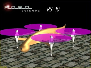
Sadly, although RoboDog was a success at demonstrating the technology, RoboScience's next project - the RS-10, an autonomous mini-helicopter camera platform to get overhead views of scenes without the expense or intrusiveness of a full-scale helicopter - was shelved after getting to the test rig stage, when a market research exercise showed that there was apparently no demand for such a thing; it is interesting to note that devices much like this are now appearing on the market, seven years later, so perhaps the idea was simply too far ahead of its time.
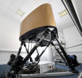
Investment became harder to find in the wake of the 9/11 terrorist attacks, and RoboScience was eventually put into hibernation while those involved concentrated on other things. Nick Wirth is now back in motor racing, with his eponymous Wirth Research company providing the technical developments behind Honda's American sportscar programme; the author is currently working with Nick on another form of robotics, namely a hexapod motion platform for a racing car simulator.
|
| Figure 5: Concept illustration of the RS-10 |
|
| Figure 6: Wirth Research's hexapod simulator |
| << Previous article | Contents | Next article >> |
| SOUE News Home |
Copyright © 2008 Society of Oxford University Engineers |
SOUE Home |